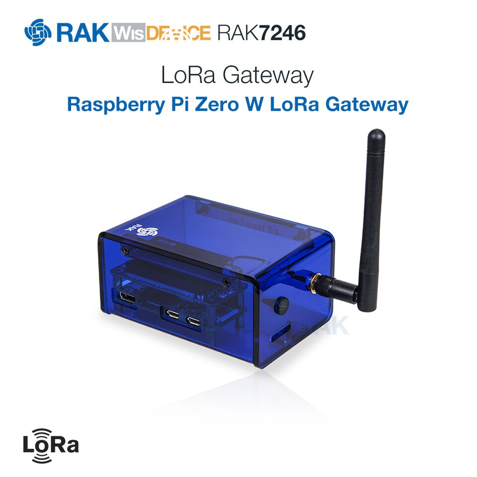


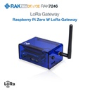


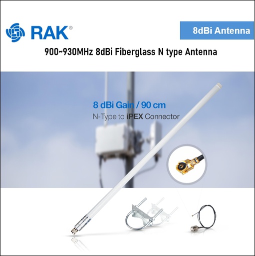
WisGate Developer D0
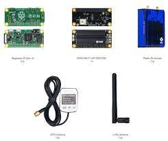
The RAK7246G is an LPWAN Developer Gateway with GPS function. It is a device composed of a the RAK2246 Pi HAT LPWAN Concentrator module and Raspberry Pi Zero W.
Terms and Conditions
30-day money-back guarantee
Shipping: 2-3 Business Days
Overview
The RAK7246G is an LPWAN Developer Gateway with a GPS function. It is a device composed of the RAK2246 Pi HAT LPWAN Concentrator module and Raspberry Pi Zero W.
The RAK2246 Pi HAT is based on a Semtech SX1308 chip, which allows for simultaneous reception over 8 LoRa channels, which cover the entirety of the international high-frequency LoRaWAN space.
The RAK7246G Developer is an ideal choice for prototype design, concept verification and demonstrations, development evaluation, and other scenarios. It is developer-friendly due to its minimalistic design that reduces cost and allows for easily accessing the internals. It is easy to set up, which makes it a good choice for both experienced and novice LoRa specialists

Features
Using SX1308 baseband processor, full 8 uplink channels and 1 downlink channel Gateway;
The Pre-installed radiator guarantees the stable thermal performance
Tx max 20dbm, Rx min -139dbm @ SF12 at 125kHz;
Covers the entirety of the LoRa high-frequency band space: RU864, IN865, EU868, US915, AU915, KR920, AS923;
Power supply 5V / 2.5A (power adapter sold separately).


Specifications for WisGate Developer D0
| Frequency band | AS923 or AU915 or EU868 or IN865 or US915 |
Once the user has seen at least one product this snippet will be visible.
Recently viewed Products
Documentation
Configuring the Gateway
You can login to the Gateway using an SSH client like PuTTY. For more details on the configuration and management of the Gateway please visit the link below:
Overview
#Description
The RAK7246G is a LoRaWAN Developer gateway with a GPS function. It is a device composed of the RAK2246 Pi HAT LPWAN Concentrator module and Raspberry Pi Zero W.
The RAK2246 Pi HAT is based on a Semtech SX1308 chip, which allows for simultaneous reception over 8 LoRa channels, which cover the entirety of the international high-frequency LoRaWAN space.
The RAK7246G is an ideal choice for prototype design, concept verification and demonstrations, development evaluation, and other scenarios. It is developer-friendly due to its minimalistic design that reduces cost and allows for easily accessing the internals. It is easy to set up, which makes it a good choice for both experienced and novice LoRa specialists.
#Features
- Using SX1308 baseband processor couple with dual SX1257, full 8 uplink channels and 1 downlink channel LoRaWAN Gateway
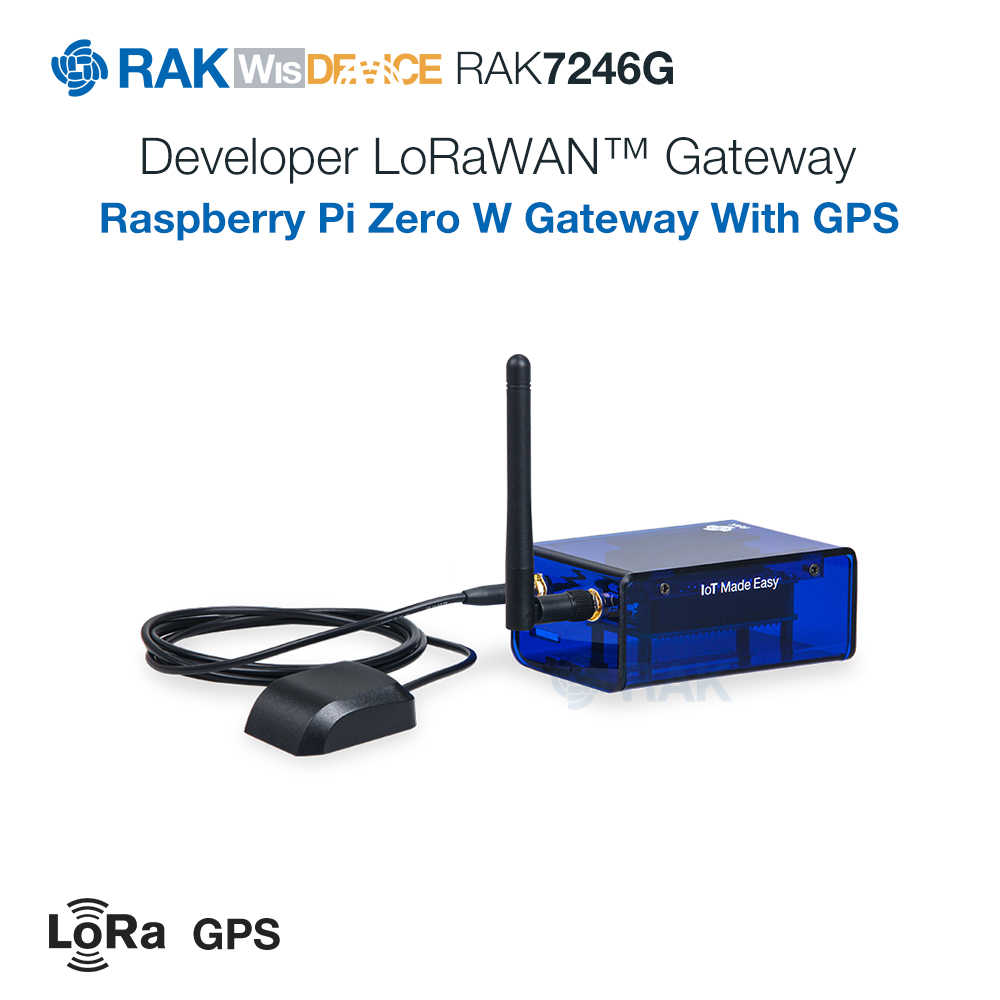
- Built-in Ublox MAX-7Q GPS module
- The Pre-installed radiator guarantees stable thermal performance
- Tx max 20dbm, Rx min -139dbm @ SF12 at 125kHz
- Covers the entirety of the LoRa high-frequency band space: RU864, IN865, EU868, US915, AU915, KR920, AS923;
- Power supply rating 5V / 2.5A (not included).
#Specifications
#Overview
The overview covers the RAK7246G board overview and the block diagram that shows how the componets operatate.
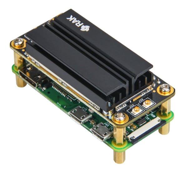
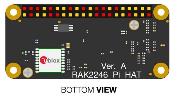
#Board Overview
#Module Overview
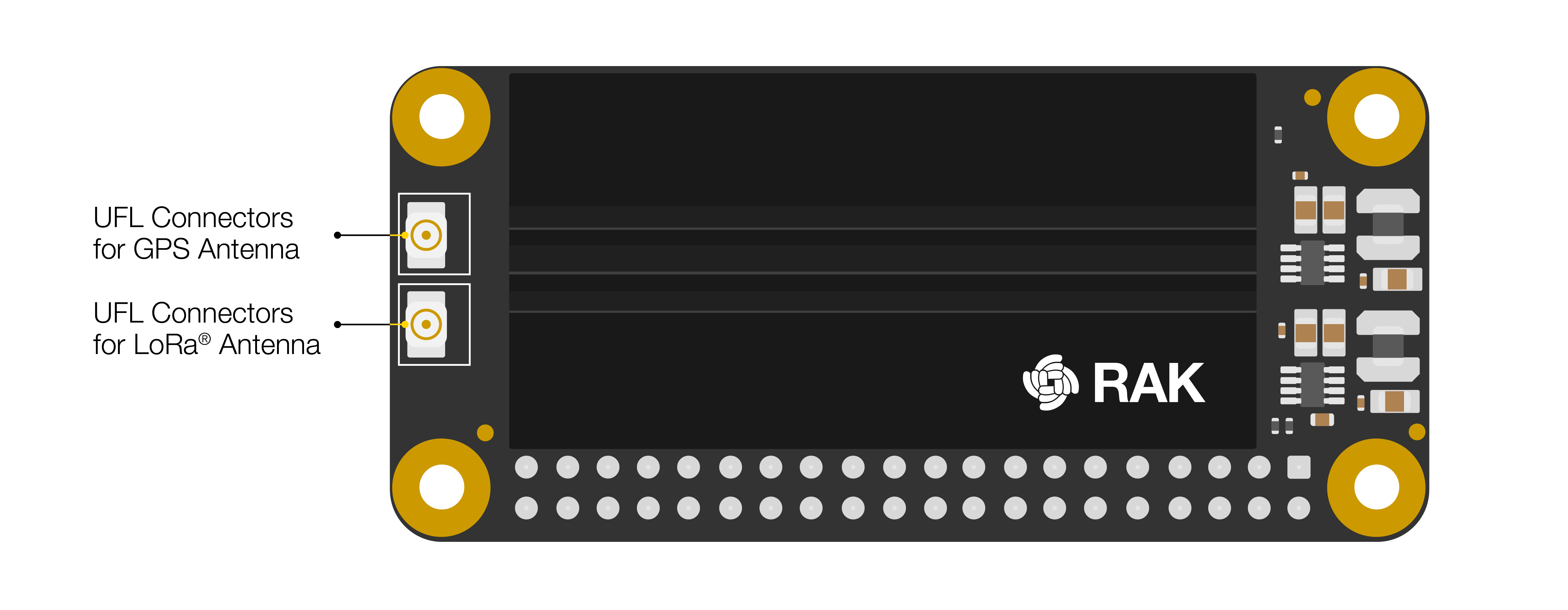
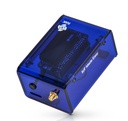
The Interfaces of the RAK7246G are as shown in Figure 2. The TF card slot is used for the SD card that houses the Firmware (based on Raspbian OS). You have two SMA connectors for the LoRa and GPS antennas. There are 3 ports on the side, which are part of the Raspberry Pi Zero W board, which from left to right are: mini HDMI, USB MicroB, and another USB MicroB/Power (please only use this to power the device with the included adapter or an equivalent one).
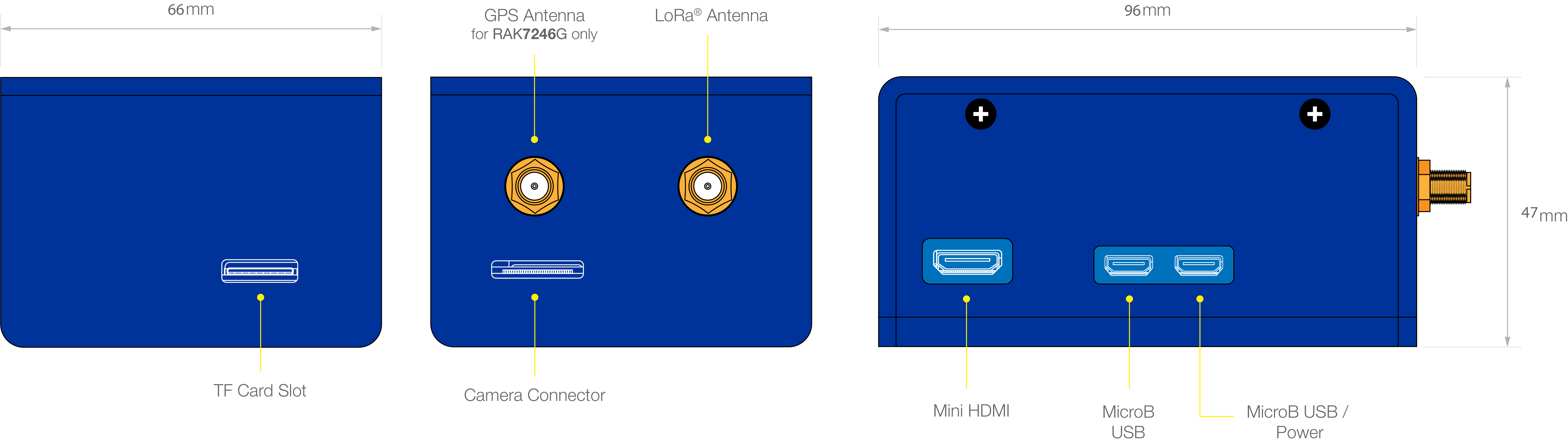
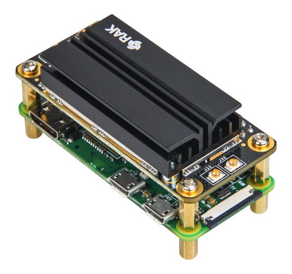
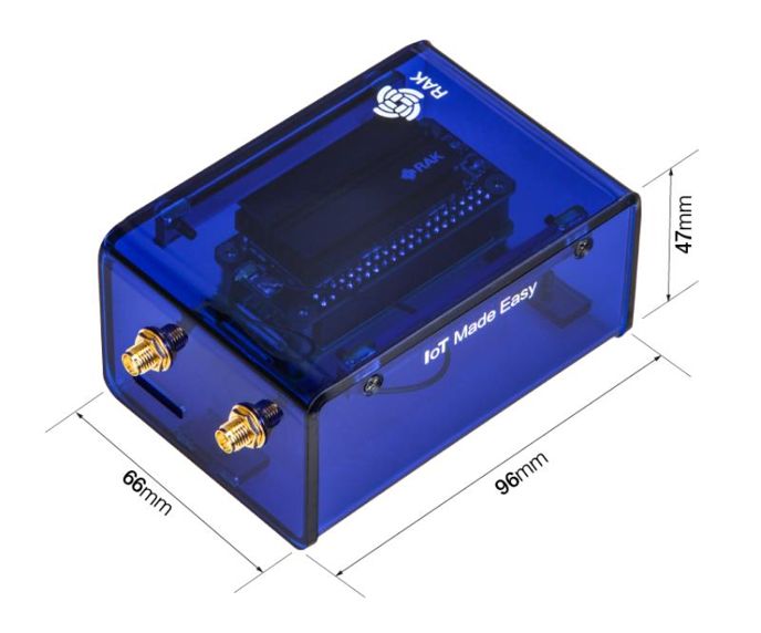
#Board Dimension
Both the RAK2246 and Raspberry Pi have the same board dimensions: 30 x 65 mm. As for the size of the Gateway with the casing refer to the Figure below.
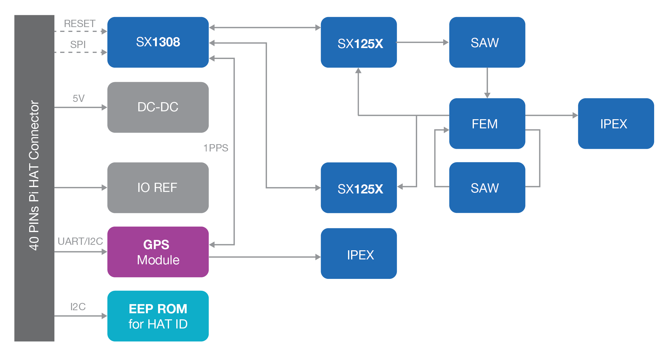
#Block Diagram
#RAK2246 Concentrator
The concentrator is available with an SPI interface:
#SX1308
The RAK2246 includes Semtech’s SX1308, which is a digital baseband chip including a massive digital signal processing engine specifically designed to offer breakthrough gateway capabilities in the worldwide ISM band.
The SX1308 is a smart baseband processor for long-range ISM communication. In the receiver part, it receives I and Q digitized bitstream for one or two receivers (SX1257), demodulates these signals using several demodulators, adapting the demodulators settings to the received signal, and stores the received demodulated packets in a FIFO to be retrieved from a host system (PC, MCU). In the transmitter part, the packets are modulated using a programmable (G)FSK/LoRa modulator and sent to one transmitter (SX1257). Received packets can be time-stamped using a GPS PPS input.
The SX1308 has an internal control block that receives microcode from the host system (PC, MCU). The microcode is provided by Semtech as a binary file to load into the SX1308 at power-on (see Semtech application support for more information).
The control of the SX1308 by the host system (PC, MCU) is made using a Hardware Abstraction Layer (HAL). The Hardware Abstraction Layer source code is provided by Semtech and can be adapted by the host system developers.
It is highly recommended to utilize the latest HAL as provided by Semtech on https://github.com/Lora-net
#Block Diagram
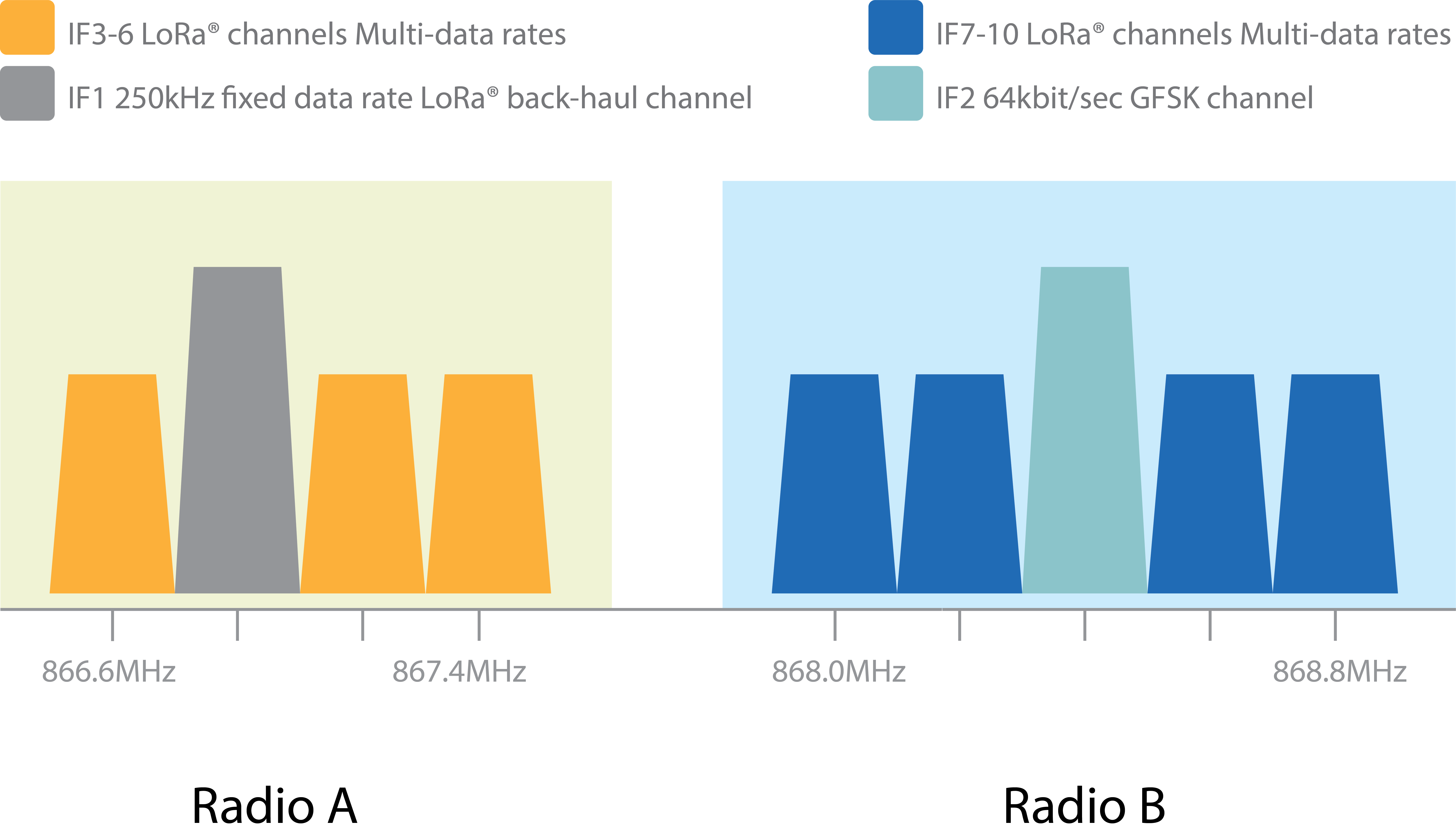
The SX1308 digital baseband chip contains 10 programmable reception paths. Those paths have differentiated levels of programmability and allow for different use cases. It is important to understand the differences between those demodulation paths to make the best possible use of the system.
#IF8 LoRa channel
This channel is connected to one SX1257 using any arbitrary intermediate frequency within the allowed range. This channel is LoRa only. The demodulation bandwidth can be configured to be 125, 250 or 500 kHz. The data rate can be configured to any of the LoRa available data rates (SF7 to SF12), but as opposed to the IF0 to IF7 channels, only the configured data rate will be demodulated. This channel is intended to serve as a high-speed backhaul link to other gateways or infrastructure equipment. This demodulation path is compatible with the signal transmitted by the SX1272 and SX1276 chip family.
#IF9 (G)FSK channel
The IF9 channel is connected to a (G)FSK demodulator. The channel bandwidth and bit rate can be adjusted. This demodulator offers a very high level of configurability, going well beyond the scope of this document. The demodulator characteristics are essentially the same as the (G)FSK demodulator implemented in the SX1232 and SX1272 Semtech chips. This demodulation path can demodulate any legacy FSK or GFSK formatted signal.
#IF0 to IF7 LoRa channels
These channels are connected to one SX1257. The channel bandwidth is 125 kHz and cannot be modified or configured. Each channel’s IF frequency can be individually configured. On each of these channels, any data rate can be received without prior configuration.
Several packets using different data rates (different SF) may be demodulated simultaneously even on the same channel. Those channels are intended to be used for a massive asynchronous star network of 1000’s sensor nodes. Each sensor may use a random channel (amongst IF0 to IF7) and a different data rate for any transmission.
Sensors located near the Gateway will typically use the highest possible data rate in the fixed 125 kHz channel bandwidth (e.g. 6 kbit/s) while sensors located far away will use a lower data rate down to 300 bit/s (the minimum LoRa data rate in a 125 kHz channel).
The SX1308 digital baseband chip scans the 8 channels (IF0 to IF7) for preambles of all data rates at all times.
The chip is able to demodulate simultaneously up to 8 packets. Any combination of spreading factor and intermediate frequency for up to 8 packets is possible (e.g. one SF7 packet on IF0, one SF12 packet on IF7 and one SF9 packet on IF1 simultaneously).
The SX1308 can detect simultaneously preambles corresponding to all data rates on all IF0 to IF7 channels. However, it cannot demodulate more than 8 packets simultaneously. This is because the SX1308 architecture separates the preamble detection and signal acquisition task from the demodulation process. The number of simultaneously demodulated packets (in this case 8) is an arbitrary system parameter and may be set to other values for a customer-specific circuit.
The unique multi-data-rate multi-channel demodulation capacity SF7 to SF12 and of channels IF0 to IF7 allows innovative network architectures to be implemented.
Hardware
The hardware specification is categorized into four parts. It includes the interfacing, pinouts, and their corresponding functionalities and diagram. It also presents the features of RAK7246G and its parameters.
#Interfaces
#External Module Interfaces
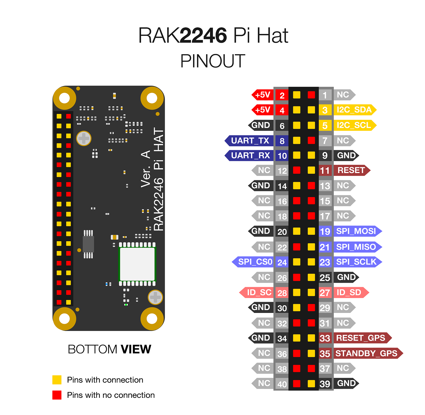
#SPI
The PINs on the connector provide an SPI connection, which allows direct access to the SX1308 SPI interface. This gives the target system the possibility to use existing SPI interfaces to communicate.
📝 NOTE
After powering up RAK2246, it is required to reset SX1308 via PIN 11.
#UART and I2C
The PINs on the bottom side provide an UART connection and I2C connection, which allows direct access to the GPS module. The 1PPS has been connected to the SX1308 internally.
#Digital IOs
There are two digital IO PINs, which give the user an interface to reset the GPS module or set it into standby mode.
#Pin Definition
Subscribe to find out all the latest updates.